Select your language

")

Select your language

Pellet burner NBE
NBE pellet burners are microprocessor-controlled intelligent wood pellet burners manufactured in Denmark. The burner can be fitted to almost all solid fuel boilers or boilers specially designed for this purpose. NBE burners are made of high quality stainless steel and are characterized by reliability and durability. Kõik põletid on varustatud juhtpaneelidega, mis on vaieldamatult turu kõige targemad juhtpaneelid.
The NBE burner has been tested in accordance with EN303-5 and EN15270 standards, and the burner has been awarded the highest possible AAA rating for the environment and energy!
NBE burners are ideal replacements for gas and oil burners. The variety of pellet burners (10-200kW) allows you to easily and comfortably heat both smaller private houses and larger industrial buildings. For those who are considering installing a system boiler + a storage zone, NBE pellet boilers do not need a storage tank! It is also much easier to install pellet heating, maintenance and less time consuming. In short, pellets do not need a accumulation tank because the pellet burner is a fully automatic robot that controls the power in real-time according to the amount of heat consumed. This means that, for example, in Spring or Autumn, when the outside is not quite cold, the burner runs at a much lower power (10% -100%). This is an economical way of heating, which, in addition to saving the pellet, also extends the life of the ignition element (the burner does not start-stop all the time). Because NBE's pellet burner is so clever, it can also manage the work of a hot water boiler. Similarly, the hot water is produced according to consumption. This is also done in the summer, which brings about significant electricity cost savings per year.
Why choose NBE?
- Our pellet burner comes with version 7 - supporting 2 heating circuits, or if needed 7-inch color touch-sensitive control panel that gives the user a different experience!
- The NBE burner automation system can handle everything in the boiler house! The control panel is capable of regulating the work of heating circuits (both radiator and floor heating), hot water boiler, solar panels, 3-way valves, pumps, compressor cleaning, pneumatic transport, chimney fan, cordless room thermostat, heat meter reader, lambda sensor and many other essential accessories.
- In addition, NBE's burner is able to show the amount of spent pellet. From the control panel it is possible to see through the special sensor how many pellets are still in the container. It is also possible to see the temperatures of the outdoor air, room, hot water boiler, radicals and returning water, boiler and burner.
- By thinking about comfort, each control panel has an internet interface, which provides an opportunity to monitor and control the entire boiler house's work over the Internet, both on a computer, a tablet and a smartphone. Look this link and peel which boilers are already connected to the network!
- The NBE pellet burner draws out in detail graphs on which you can see everything happening in the boiler house in real time, while you can see the whole history of the heating season.
Do not waste fuel and time every evening cleaning the boiler, not to mention choping trees, wrapping, drying, etc. Perhaps you are going to fill the hopper with a pellet once a week and empty the ash from boiler. In the case of boiler equipped with an automatic heat exchanger cleaning mechanism and a compressor cleaning system, boiler and a burner are maintenance-free.
Solid fuel boiler working principle
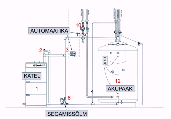
| 1 | Solid fuel boiler | 10 | Circulation pump |
| 2 | Safety valve | 11 | Mixing valve TERMOMIX (motor unit AUTOMIX-55) |
| 3 | Heating controller AUTOMIX 30Q | 12 | Accumulation tank |
| 6 | Loading units TERMOVAR or custom made |
The solid fuel boiler system presented below is whole, which ensures the proper functioning of all system components by using minimum number of required components and assemblies in the solution.
This small house boiler with all the necessary components is the best solution for the construction of a solid fuel boiler system.
System introduction.
The main components of the system are shown in the figures in the following pictures. It is possible to use solutions with one or more accumulation tanks depending on the size of the heated building and the possibilities of installing the accumulation tanks. The purpose of the system is to ensure the temperature of the water required for central heating as well as the hot water consumption, the minimum fuel and time required for day-to-day circulation.
Working principle
The proposed central heating system is divided into two separate parts for its purpose and purpose of operation, which are interconnected with a warm accumulation tank. The first part, or heating part, consists of a boiler, a boiler mixing unit and a connecting pipe. The purpose of the heating part is to ensure that the correct (sufficient) temperature, regardless of consumption, is constantly maintained in the accumulation tank . The second part, that is, the consumption part, consists of a heating system circulator, a heating pipe and heating elements (radiators, floor heating contours, etc.) and their regulators and valves. The purpose of the consumption section is to ensure the warmth of the premises (including domestic water) by using energy stored in the accumulation tank in a sustainable manner.
System
The system has three circuits circulating.
1. The first boiler circulator circuit consists of a boiler (1), a system safety valve (2), a mixing unit (6) between the boiler and the storage tank, and the tubes connecting them. The purpose of this circulator circuit is to reach the boiler's operating temperature as soon as possible in order to prevent excessive soiling and heat loss in the boiler as well to extend the lifespan of the boiler. The operation of this circle becomes clearer when getting to know more about the mixing unit between the boiler and the storage tank construction and operation.
2. The second, or accumulation circulation circle, is the next one in line. Adding storage tank, tanks (12) with associated equipment and piping to the system. The second ring starts to work when the boiler has reached its operating temperature (& gt; 65C) and the ring unit is opened, opening the path for the hot water into the accumulation tank. The accumulator tank has heat exchanger for the production of domestic water, which is a spiral tube, connected to the water pressure relief valve and the domestic water mixing unit. The domestic water mixing unit is a conventional three-way thermocouple that regulates the temperature of the hot water entering the DHW system.
3. The third, building circulation consists of a circulation pump (10), a mixer valve (the 3-way valve) (11), thermometers and automation equipment (3). They control the temperature and circulation of the central heating water passing through the central heating circuit of the building (floor heating elements, radiators, piping, etc.).
The proposed solution allows the rooms to be heated up quickly in a cooled system, as the hot water for the central heating circuit of the building is taken from the boiler from the pipe that is connected of the storage tank. Therefore, if the circulation pump (10) is running and the 3-way valve (11) is opened for circulation, the required amount of hot water is firstly taken directly from the boiler. The remaining hot water is then directed to the accumulation tank (12). When the boiler has burned off - the heating is completed, the water cycle from the accumulation tank continues for the central heating circuit of the building.
The temperature of the storage tank at the end of heating shuld be between +85 and + 95 ° C.
© 2002, instructions on the website of BAXI AB.
Choosing boiler and accumulation tank
See the table below to select the right boiler and battery tank
The data is true with accumulator heating system in the case where the heating mode of the building is controlled by the heating system. The sizes considered are suitable for all houses. The heating frequency depends on the thermal insulation of the house. The choice is made on a heated surface area, with a height estimate of 2.5 to 2.7 m. The use of 50 cm firewood is common. Cast iron boilers suitable for 50 cm firewood have to be at least six ribs. A larger boiler can also be installed. The larger boiler will reduce the heating time and the number of heating cycles!
| Heated area m2 | up to 100 | 100-120 | 120-150 | 150-180 | 180-200 | 200-220 | 220-260 |
| Accumulation tank (L) | |||||||
| 100% radiator heating | 1000 | 1200 | 1500 | 1800 | 2000 | 2200 | 2500 |
| 50% rad + 50% floor heating | 700 | 800 | 1000 | 1200 | 1400 | 1600 | 1800 |
| 100% Floor heating | 550 | 720 | 900 | 1080 | 1200 | 1300 | 1400 |
| UNI | 4 | 5 | 6 | 7 | 8 | ||
| Boiler power (kW) | 20 | 28 | 35 | 44 | 53 | ||
| Firewood lenght max. (mm) | 330 | 440 | 550 | 660 | 770 | ||
| Capacity of the combustion chamber (dm3) | 51,6 | 70,3 | 89,1 | 107,8 | 126,5 | ||
| VIADRUS U-26 | 4 | 5 | 6 | 7 | 8 | 9 | 10 |
| Boiler power (kW) | 20-24 | 27-32 | 35-40 | 43-48 | 50-56 | 58-64 | 66-72 |
| Firewood lenght max. (mm) | 295 | 405 | 515 | 625 | 735 | 845 | 955 |
| Capacity of the combustion chamber (dm3) | 37 | 51 | 64,5 | 78 | 91 | 105 | 118,5 |
Loading units for boiler
Katla segamissõlm
The mixing unit is a device based on the thermocouple operation, which is installed between the boiler and the accumulation tank for keeping the boiler operating temperature automatically. The mixing unit is especially useful for solid fuel boilers. Keeping the correct boiler temperature and increasing the fast temperature after ignition will significantly reduce the boiler's corrosion and soot, as the condensation time from the boiler and the smoke pipes heating up will reduce to to ten times ( NB! 5 mm soot on the boiler wall eaquals about 15 mm thickness layer of stone wool ) The use of the mixing unit prevents the formation of micro-cracks and consequently the leakage or breakage of the boiler.
Starting
It is advisable to control (start and stop) the mixing unit circulation pump using a contact thermometer located on the smoke duct. If the boiler lights up, the flue gas contact thermometer turns on the circulation pump. Therefore, if the flame goes out in the boiler, the flue gas temperature drops, and when it falls to the minimum regulated value of the contact thermometer, the pump switches off.
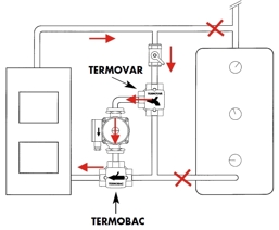
Working principle
The thermostatic valve of the mixing unit warms up by the returning hot water from boiler. 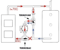 When warming up, the thermostatic valve opens and allows cool water in from return line. The thermal opening depends on the temperature of the water around the thermocouple, which means that the temperature of the water from the thermostatic valve is always kept constant. Generally, thermocouples operating at 61C, 72C are used. The return temperature of the boiler is maintained at a temperature between 60 and 65 ° C. Due to the pressure generated by the circulation pump, the reflux stop valve (TERMOBAC) closes by blocking the cool water coming back from the battery tank or the heating system directly to the boiler. However, the hot water coming from the boiler is pumped through the thermostatic valve back to the boiler. Water only moves in the small circle of the boiler. The boiler is heating up quickly and evenly.
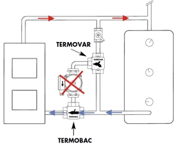
Free flow
If the circulation pump is stopped (in the event of a power failure etc), the water pressure from the pump will drop, causing the shut-off valve to open due to natural circulation, thus allowing the system to circulate naturally, protecting the boiler from overheating and breaking.
© 2002 Guides on the ACASO AB website.
Mixing units for heating
The aim of the heating mixing unit is to ensure the correct temperature of the heating water needed for heating the premises at any given time, depending on the temperature of the ambient air and room, as well as the prescribed program.
Principle
The blending unit in the following further, the circulator consists of a circulation pump, a regulating 3-t valve, a setting valve, thermometers, and a building's thermal automation unit. The work of the mixing unit is controlled by the building's automatics (eg AUTOMIX 20, AUTOMIX 30, etc.) which, according to the ambient air temperature and (or) indoor air temperature, controls the position of the control valve (3-way valve). As the temperature drops, the 3-way valve opens for more hot water to the system, which increases the temperature of the circulating water in the building's heating circuit (radiator, floor heating, etc.), thus ensuring the heat needed in the building. As the outside and the building's internal air temperature rises, the 3-way valve closes hot water and opens for more returning cold water, which causes the temperature in the building's heating circuit to drop. This prevents the building from overheating, ensuring a warm, sustainable use.
The following figure shows the operation of the central heating circuit.
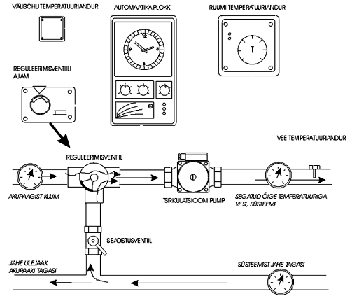
The entire operation of the system is monitored through thermometers installed on the pipelines, boiler and accumulation tank.
© 2002, Guides on the ACASO AB website.